Q: I am designing an office complex. Should I be doing Neher-McGrath calculations?
A: Every project needs to be analyzed based on its specific operating perimeters, but the simple answer is No. Anytime a current is running through a resistance, heat is produced; however, the standard de-rating factors found in NEC 310.16 are more than adequate to compensate for building with standard load factors, like offices. These specific areas should be analyzed if any building areas have a higher than building average load factor.
Q: How much does it cost?
A: Every solution is unique based on many site-specific variables. Some solutions will require only a rearrange of conduits in a specific duct bank; others may require a larger conductor size, Added Conduits, or a LowRHO backfill. But keeping your conductors within their temperature parameters is not only a requirement of the NEC, but it lowers your overall energy use by illuminating some of your I2R losses. Also, if the ductbanks are run directly under the building slab, the conductors' heat will be transferred to the building. This added heat may be beneficial in some specific environments. But in most environments, this is heat that will have to be removed from the building. Based on this information providing the correct Neher-McGrath solution can save money over the life of the project.
Q: Will your LowRHO® backfill increase ampacity and save me money?
A: Not always. In some situations, LowRHO® is not a good solution. Many variables need to be considered. In some conditions, the best answer is to modify the duct bank configuration or placement. There are specific configurations where LowRHO® will make the heating issue worse. Every solution is site-specific.
Q: Back as little as 5 years ago, these calculations were rarely performed. Why is it an issue now?
A: One reason is that as rack density gets higher and the datacenter becomes fully loaded, this is becoming more of an issue. When a data center is built, the maximum design load is rarely on-line on day one. Typically we see day one load in the 25-50% range. Over time these loads are increased. A typical data center may not be operating at the design load for years after completing the project. We have been involved in several projects as expert witnesses and analytical consultants where this exact thing happened. We have seen this repeated, and we know that there are still many data centers out there now that are still operating below their design load. As these datacentres hit and run at full load, we anticipate this issue to arise.
Q: How will this process affect my construction schedule?
A: If addressed early and adequately, there will be no effect on the construction schedule. It is only where the issue is not addressed that there can be significant effects on the schedule. The key is to talk about it early in the design process and determine if this is an issue for your project. Most projects like schools, offices, and general commercial projects will not be an issue.
Q: How do I determine if I have an issue?
A: Ask yourself these questions:
1. Is this Project a critical environment?
2. Is the design of this project based on a high load factor model?
3. Will the design require large duct banks?
If the answer to any of these questions is yes, ask an expert to review your project further. We can recommend an engineering company that specializes in this type of analysis.
Q: Can I buy some software and do my calculations?
A: There are abundant software packages sold today that perform this complex calculation. Some of these systems are very good, and some are weak or poorly designed. The package you buy is dependent on the complexity of calculation you need to perform and how much tolerance you have for a steep learning curve, and your budget. Also, there are numerous variables that you need to know and understand before you can even start the calculation. Let's say you have the software and the required system variable, and you do a calculation. Now you have the results, and you are halfway home. Much like an X-Ray, the information is only as good as the Dr. who analyzes it. It takes years to truly understand all of the results and find the best solution. Also, these calculations can only be performed under Engineering Supervision, Per NEC 310.15. We are fixing more and more issues caused by engineers not truly qualified to interpret the calculation results. Yes, you can do the calculation yourself, but with your underground conductors being your business's lifeblood, why would you?
Q: Since RHO is relative to moisture content, how can I determine soil's expected moisture content directly around conduits or a duct bank?
A: This is a complicated question. ASTM D5334 - 08 describes the procedure for determining RHO value bases at a given moisture content. However, it provides no direction as to what moisture content will actually exist at the installation location at a future time. Underground heat sources, such as ductbanks, cause drying of the soil around the source. Water evaporates from the warmer soil and condenses in cooler locations. In soil with good thermal stability, an equilibrium condition will develop where the liquid return flow matches the vapor distillation from the heat source. It is essential to state that the moisture directly around the conduit or duct bank will be less than the moisture content if the heat source did not exist even in this equilibrium condition. In soil with poor thermal stability, this equilibrium condition is never achieved, and soil continues to dry to 0% moisture or until the moisture is replaced. It is a huge but all too common mistake to assume that the RHO value should be based on native moisture at the install time or in-situ moisture. Numerous factors determine how fast moisture will leave a heated area, but it is not unusual with load factors above 90% for soil exposed to 75°C-85°C conduit to lose 50% of their moisture within the first 9000 hours of operation. Three of the most common types of installations are as follows:
Type 1 - Under a structure with a vapor barrier.
Type 2 - Exterior with full exposure to the environment.
Type 3 - Exterior covered by road, concrete, or other non-pours material.
In a type 1 installation, the vapor barrier mitigates some moisture loss. You will still lose moisture over time, but this loss will be much slower.
Type 2 is a mixed bag. If your installation is in a location where it rains, you are constantly replacing some of the lost moisture. If, however, you are in a desert environment, the soil will continue to dry faster than would be expected in a type 1 location. Additionally, in a desert, the hottest time of the year is also the driest. During the time of year, you need the most power at the highest load factor.
A type 3 allows moisture to leave but none to reenter. Under a roadway or covered canopy, the soil will dry out like in type 2, but because rainwater cannot be absorbed into the ground, the moisture cannot be replenished at all.
There are tests that can predict thermal stability, including a "2 zone test" and a "Time to dry out test" but it is important to note that ASTM or IEEE recognizes neither of these tests. Having an engineer that understands these conditions is critical.
Q: The NEC uses 90RHO for the earth. Is this a safe number to use?
A: The simple answer is No. The NEC arrived at these values from AIEE Paper 57-660, The Calculation of the Temperature Rise and Load Capability of Cable Systems, by J. H. Neher and M. H. McGrath that stated the average soil in the US was 90 RHO in-situ. Average RHO in the US, while an interesting statistic, is a useless piece of information for designing a specific site. Imagine engineering a site based on the US's average voltage or designing a drainage system in Seattle based on the average rainfall in the US. But it gets worst, even if we test, and the soil on a specific site is, in fact, 90RHO In-situ, we know that once we install a heat source, i.e., conduit system, the soil will dry out. As engineers, we are interested in the RHO of the soil when we install the conduit system only as a reference point. We need to know the soil RHO value around my conduits after the soil has been exposed to the design temperature for 10 years or 20 years. If you design based on 90RHO and the actual RHO is higher than that, your system is at risk. If your site has a lower than 90RHO, you are throwing money away by installing too many conductors.
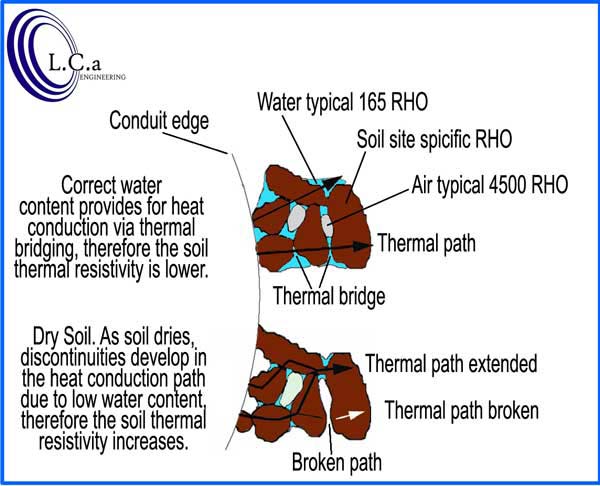
Q: Why are moisture content and compaction so critical?
A: Moisture content and compaction are critical because they provide an unbroken path vie thermal bridging for heat escape. The accepted RHO value for water is about 165. Air, on the other hand, has a RHO value of about 4500. If soil is not compacted correctly, then there is more air between the backfill partials. This air gap causes breaks in the thermal bridges and increases the overall heat resistance of the fill. It is important to note that if the soil is not compacted correctly, then the maximum RHO of a given sample tested per IEEE-442 at 0% moisture can be significantly exceeded. See the illustration below for an example.
Q: What is thermal capping?
A: Thermal capping is a situation that can exist when the soil is stratified at the installation location. When you look at a soil report, you want to know the RHO value at the depth the conduit or duct bank installation depth. But you also need to look at all the soil above the installation depth. If the soil is stratified, then there could be soil layers above the conduit at a higher RHO value than the soil at the installation depth. This is known as the thermal capping or thermal blanketing effect. The engineer must take the soil above the conduct into account and not just use the RHO value at the installation. This effect is difficult to quantify and is another reason that the calculations should only be performed by an engineer highly experienced in Neher-McGrath's specifics.
Q: What other issues are there with stratified soil?
A: Another issue that we need to be aware of with stratified soil is spoils mixing. When a trench is excavated, the trench's spoils are typically dumped on the side of the trench. Typically the most cost-effective way of digging a trench is vertical. The trench is dug to its greatest depth in a location, then the backhoe is moved, and the next portion of the trench is dug to its greatest depth. This process is repeated for the length of the trench. If the soil is not stratified, then this may not be an issue; however, in stratified soil where there are varying values for RHO, the spoils from differing stratified layers are dump in the same pile on the side of the trench. If this material is intended to be used for a back full above the duct bank, we need to be aware that some RHO averaged in the spoils pile. So once again, we cannot just look at the RHO values from the level that the duct bank is installed.
Q: Is the Neher-Mcgrath method the only way to calculate underground ampacity?
A: No. Neher-Mcgrath method is the industry standard calculation, but there are situations where the Neher-Mcgrath method falls short. The Neher-Mcgrath method is based on ampacity that is static over a given time. In a Dynamic current situation, the Neher-Mcgrath method is a bit conservative. The dynamic current analysis is best done using the KEMA model. This model is designed for transmission-grade power and applies to medium voltage and high voltage cables where the operator (typically a utility company) needs to know how much current they can push through a given cable over the next 24 hours.
The model can predict cable temperatures in the future (based on an expected loading) or calculate the maximum ampacity for the next hours or days. By using these mathematical techniques in a control room setting, for example, the following can be calculated:
The current cable can transport over the next 24 hours.
The length of time the cable can transport a given ampacity. The KEMA dynamic thermal model has been comprehensively verified in many situations and cable types, including oil-filled and polymeric cables in the voltage range from 10 to 150 kV, and installed in various cable environments. Thus, the model is well-suited for use in a cable ampacity management system to determine on-line circuit loading.
Q: How do I ask a question?
A: Email Us.Info@neher-mcgrath.com |
|
.: Professional Engineering
Neher-McGrath are specialized and complicated calculations. We highly suggest that all results and calculations be made under the guidance of a licensed professional engineer specializing in this type of work. NEC 310.15 (C) Engineering Supervision indicates that these calculations should be performed under engineering supervision.
.: Software:
There are several software packages available that calculate the Neher-McGrath equations. Each of these packages has its pros and cons.
.: Professional Articles :
-Heating Pure Power Spring 08
-Duct Bank Heating Calculations
.: Special LowRHO® concrete Mix:
High strength LowRHO� Mix Design
Low strength LowRHO� Mix Design
.: RHOMON® Conduit Thermal Couplings:
RHOMON� Conduit Thermal Couplings are specially engineered pieces of conduit that are placed in your duct bank during installation. These units monitor temperature and can be set up in a self-contained system or tied into the building BMS system
|