neher-mcgrath_about
neher-mcgrath_products
neher-mcgrath_FAQ
neher-mcgrath_links
neher-mcgrath_links
   

.: Neher-Mcgrath RHOMON® System:


RHOMON® Conduit Thermal Couplings are specially engineered pieces of conduit that are placed in your duct bank during installation. These units monitor temperature and can be set up in a self contained system or tied into the building BMS system.


Neher-Mcgrath rhomon


.: Professional Engineering

Neher-McGrath are specialized and complicated calculations. We highly suggest that all results and calculation be made under the guidance of and licence professional engineer that specializes in this type of work. NEC 310.15 (C) Engineering Supervision, indicates that these calculations should be performed under engineering supervision.

.: Software:

There are several software packages available that will calculate the Neher-McGrath equations. Each of these packages has its pros and cons. Please feel free to email us with your particular project requirements and we can help you find the software package that best suits your needs. Email Us

.: Professional Articles :

Heating- Pure Power Spring 08
Duct Bank Heating Calculations are Essential for Critical Environments (Data Centers)

.: DuctShow©:

By downloading you agree that DuctShow© movies are Proprietary and for demonstration purpose only. The information shown in the DuctShow© movies below are NOT applicable to any and all real world installations.

.: Special LowRHO® concrete Mix:

High strength LowRHO® Mix Design - Compressive Strength psi 3000

Low strength LowRHO® Mix Design- Compressive Strength psi 100-250


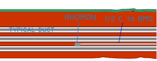
.: RHOMON® Conduit Thermal Couplings:

RHOMON® Conduit Thermal Couplings are specially engineered pieces of conduit that are placed in your duct bank during installation. These units monitor temperature and can be set up in a self contained system or tied into the building BMS system


.: thank you!


This site a subsidiary of Lane Coburn and Associates, LLC. The Industry Standard for Neher-McGrath Calculations © Copyright LCA 2023, All rights reserved.
Lane Coburn
   

Underground Cables Need a Proper Burial

Apr 1, 2003 12:00 PM By Deepak Parmar and Jan Steinmanis, Geotherm Inc. Overhead systems are out in the open, so it is easy to detect and fix design and installation problems. Underground problems, however, are out of sight and out of mind, at least until cables start failing. Although utilities design their underground circuits for a 30-year life, improper installations often can lead to premature field failures. Unless you lay your cables to rest properly, they may come back to haunt you. Here's a brief example. A wind-generating farm was installed with underground cables tied directly to a main feeder cable. Unfortunately, the cables were simply placed in a trench using native soil backfill with minimal soil compaction. Ampacity calculations were performed using typical soil values, but thermal properties were not measured. Since wind turbines operate almost continuously, the feeder cable often ran at maximum capacity. The heat generated from the feeder cable dried out the surrounding soil completely. Because the native soil was poorly compacted fine silt, it acted like an insulating blanket and the cable failed prematurely. A significant source of potential problems with underground circuits is the improper selection and installation of thermal backfill materials. To prevent premature failures, you must ensure you place cable systems in a hospitable environment. Too few utilities have stringent specifications or quality-assurance programs for installing cable-trench backfill; this often leaves the decision up to the civil contractor. The effects of poorly installed thermal backfills and soils may not be evident for many years, until cable loads increase and temperatures rise beyond allowable levels, resulting in cable failures. The remedial cost of removing and replacing poor backfills is high, especially under paved roads. The loss of revenues from derating a system may be even higher. Installing a new circuit may be the only, albeit expensive, option. Importance of Soil and Backfill All the heat generated by an underground power cable must be dissipated through the soil. This is quantified by the soil thermal resistivity (or thermal rho, °C-cm/W), which can vary from 30 to 500°C-cm/W. Electrical engineers understand the performance of the cable quite well, but to most, the soil behavior is a mystery, usually handled by using a thermal backfill with a supposedly "safe" thermal rho. The ability of the surrounding soil to transfer the heat determines whether an operating cable remains cool or overheats. Improving the external thermal environment and accurately defining the soil and backfill thermal rho commonly results in a 10% to 15% increase in cable ampacity, with 30% improvements noted in some cases. You can address potential problems by measuring the native soil's thermal properties and by using properly designed and installed corrective thermal backfills in the cable trench. In recent years, we've learned that using thermal probes connected to a Thermal Property Analyzer (EPRI EL-2128) can accurately measure the thermal rho in the field and laboratory. The use of a soil thermal rho of 90°C-cm/W has become ingrained in cable engineering practices. Soil studies performed in the 1950s found this was a "safe" value for most moist soils. This value is commonly used for distribution cables, where cable loads are usually low and the native soil is used as the backfill. For transmission cables, it is assumed that the "thermal backfill" placed around the cables will be much better than the native soil and that it will have a thermal rho of less than 90°C-cm/W. Thermal Backfills Most moist soils (with the exception of organic clays and silts, volcanic soils, peat and fills with ash and slag) have a rho of less than 90°C-cm/W. Moist sands, which are commonly placed around transmission cables, may even have a rho of less than 50°C-cm/W. The critical word is "moist." Many soils, especially uniform sands, can dry substantially when subjected to heat from the cables. The thermal rho of a dry soil would exceed 150°C-cm/W, and possibly approach 300°C-cm/W for a dry uniform sand. (The dry thermal rho of a properly designed and installed thermal backfill should be less than 100°C-cm/W and possibly as low as 75°C-cm/W). In fact, a contractor, if left to his or her own devices, most likely would use readily available fine sand or concrete sand as the backfill. From a construction viewpoint, this sand makes an inexpensive and excellent bedding material, but thermally, it is very poor because it dries out easily under high cable loads. Unfortunately, over the years utilities have used many unsuitable sands or "thermal backfills" because of ease of installation and availability. Several route thermal surveys of existing circuits installed before 1980 confirm this practice. Almost any sand, when moist, will give a reasonably low thermal rho. The crucial aspect is how easily it dries when subjected to cable heat loads. Soils in semi-arid climates are naturally quite dry, so the assumption of a moist soil is not valid. It doesn't take much to dry these soils completely. In many parts of the country, the soil mineral and consistency is such that there is a high intrinsic thermal rho. Soil that is not properly compacted in the cable trench will be less dense and have a substantially higher thermal rho. Even distribution or low-voltage cables that are continuously under full load may dry the soil. Cables that are near other heat sources, such as steam mains, will experience higher ambient temperatures, and if in the vicinity of other cables, will experience mutual heating and run hotter. The thermal rho is important not only for transmission cables but also in any situation resulting in high heat generation. The assumption of a soil and backfill thermal rho of 90°C-cm/W may be erroneous, possibly leading to long-term problems when the cable is heavily loaded. Poorly compacted trench backfill is a major problem. Not only is the thermal rho of uncompacted soil significantly higher, but the loose soil will dry more easily, which increases the possibility of thermal runaway. Corrective Thermal Backfills Generally, native soils do not make good thermal backfills because their thermal rho values are poor, or they are difficult to properly re-compact in a cable trench. There are also problems associated with stockpiling, screening of debris, and contamination of good soil with organic topsoil. In the long run, the operational reliability gained by placing a classified thermal backfill around the cable has advantages over the variability and uncertainty of recompacted native soil. Compacted granular backfills can have good thermal properties. Since most of the heat conduction is through the soil mineral particles and their contacts, one must ensure a high-density soil mixture to maximize these contacts. A well-graded sand to fine gravel can be a good thermal backfill when compacted to its maximum density as determined by a laboratory standard Proctor test (ASTM D698). The total cost of a compacted backfill must include material and transportation costs, as well as installation labor and quality-assurance costs. The one often-neglected factor about compacted backfills is the need for quality assurance during installation. If the gradation of the backfill is not correct (sieve analysis ASTM D422), or it is not at the optimum moisture content (ASTM D698), or not enough compaction effort is applied, or the backfill lifts are too thick, then the maximum density will not be achieved and the thermal capability degraded. Cement stabilized sand frequently has been used as a cable trench backfill in many countries. A typical mix design consists of 14 parts sand to one part cement, mixed with about 8% water. If the correct sand is used and properly installed, this material can have acceptable thermal performance. However, this backfill is quite strong and thus would be difficult to excavate. Quality control is required during mixing and installation, otherwise the thermal performance cannot be assured. Many North American utilities have been using stone dust or crushed stone screenings as thermal backfill. If well graded and of the right mineral type, it provides a low and stable thermal resistivity when compacted at optimum moisture content and density. It does require thorough testing to establish density, moisture and thermal performance, and a good quality-control program to ensure proper installation. With compacted soils, maximum soil density is needed in the restricted trench areas near cables or around cable pipe groups where proper compaction is difficult. Yet, it is precisely in these zones adjacent to the cables, where the heat flux is highest, that suitable compaction is most important to ensure maximum heat dissipation from the cables. Fluidized Thermal Backfills Over the past 10 to 15 years, we've seen great acceptance of fluidized thermal backfills (FTB™), which are formulated to meet thermal resistivity, thermal stability, strength and flow criteria. This free-flowing, controlled-density fill is ideal for hard-to-access areas, such as narrow trenches, small diameter tunnels or areas congested with many underground services — basically where mechanical compaction is not feasible or practical. While the material cost of FTB may be higher, it should be considered for general usage because of its assured quality and quick installation, thus speeding up construction and decreasing overall costs, which are important factors when working in busy city streets. FTB is a slurry backfill consisting of medium aggregate, sand, a small amount of cement, water and a fluidizing agent. FTBs can be formulated using locally available aggregates. The component proportions are chosen by laboratory testing of trial mixes to minimize thermal resistivity and maximize flow without segregating the components. Be wary of commonly available "controlled density fills," "flowable fills" or "slurry backfills," which use large volumes of fly ash or sand. These may meet the mechanical and flow requirements for trench backfilling, but too often they provide totally unsuitable thermal performance. Fluidized thermal backfills should be formulated and tested only by soil thermal specialists who understand the tricks of the trade in making thermal measurements. Fluidized thermal backfills do not have to be compacted; they flow in a fashion similar to concrete. In fact, FTB is typically supplied from concrete trucks, and may be poured or pumped, and seldom requires any special shoring or bulkheading. It solidifies to a uniform density by consolidation, with excess water seeping to the top. Regular FTB can be pumped up to 150 m (500 ft) using conventional concrete pumping equipment and greater distances with special modifications. It hardens quickly so that the ground surface may be reinstated the next day, but the low strength (100 to 250 psi [0.7 to 1.8 MPa]) allows it to be broken up with a backhoe if required. If a higher strength is required, the cement content can be increased and the water adjusted without degrading the thermal performance. FTB will flow readily to fill all the spaces, without vibration, yet harden quickly. Future settlements are negligible. It also affords mechanical protection for the cables or cable pipes and provides support for underground and surface facilities (road pavement). FTB has good heat dissipation properties even when totally dry. Depending on the mix design, typical thermal rhos are 35 to 40°C-cm/W wet, and 70 to 100°C-cm/W dry, with excellent thermal stability. The FTB can be formulated for use in both flat and hilly terrain. Thicker, slower flowing mixes can be formulated when addressing an area with a significant slope. Backfills … The Right Way The use of a well-designed thermal backfill can enhance the heat dissipation and increase the allowable ampacity of an underground power cable, as well as alleviating thermal instability concerns. The corrective backfill will reduce the heat flux experienced by the native soil so that it will not dry out; therefore, the stability of the native soil is no longer a concern. A good backfill should be better able to resist total drying and also have a low dry thermal rho if it is completely dried. It should be available at a reasonable cost, and be easy to install and easy to remove if required. The thermal backfill must be laboratory evaluated and include specifications for mineral quality, gradation (sieve analysis), thermal dryout curve and optimum density. Typically, the entire trench width is filled with thermal backfill to a minimum height of 300 mm (12 inches) above the cables. For poor native soil conditions or heavily loaded cables, the thickness of the backfill can be increased to maintain a low composite thermal rho. A fluidized thermal backfill is the ideal way of providing a high-quality cable backfill. Deepak Parmar is president of Geotherm Inc. From 1960 to 1978, he worked on various civil engineering (soil and rock mechanics) projects in the United Kingdom and Canada. Since forming Geotherm Inc. in 1978, Parmar has worked solely on underground and submarine power cable projects. He received the BS degree in civil engineering from Woolwich Polytechnic, United Kingdom, in 1966, and the Diploma in Management Studies (DMS) from Slough, United Kingdom, in 1972. He is a member of the Engineering Institute of Canada, Canadian Society for Civil Engineers, Canadian Geotechnical Society, Canadian Society for Electrical and Computer Engineers, Tunneling Association of Canada, IEEE/PES/ICC, Canadian Electrical Association and CIGR…. Jan Steinmanis is vice president of Geotherm Inc. He received a B.A.Sc. degree in civil engineering from the University of Toronto, Canada, in 1975. From 1976 to 1982, Steinmanis worked as a research engineer with Ontario Hydro, where he worked on several civil engineering projects and on the Electric Power Research Institute (EPRI)-funded projects for the Development of Thermal Property Analyzer. He also conducted several research projects, including the soil geotechnical-thermal properties database for Canada (a Canadian government-funded project). He is a registered professional engineer. Elements of a Cable Route Thermal Survey • Perform in-situ thermal rho testing and sampling of the native soils. This may be done in conjunction with any required geotechnical testing, such as for manholes. Review any available soils information so test locations cover all the soil types. • In the laboratory, perform thermal dryout tests (thermal rho vs. soil moisture) on select samples. This will define the thermal rho for drier soil conditions. • Source and design the fluidized thermal backfill (or compacted granular backfill) based on locally available materials. This also will include a thermal dryout curve. • Choose the design thermal rho values for the native soil and thermal backfill based on the lowest expected soil moistures. • Use a computer cable design program to optimize configuration of cables, trench size and thermal backfill envelope. Soil Components Description Thermal Resistivity Dry (°C-cm/W) Soil Grains Quartz 12 Granite 30 Limestone 40 Sandstone 50 Shale (sound) 60 Shale (highly friable) 200 Mica 170 Others Ice 45 Water 165 Organics 500 Oil (petroleum) 800 Air 4500 Thermal Stability Thermal stability describes the ability of a moist soil to maintain a relatively constant thermal rho when subjected to a cable heat load, thus preventing a power cable from exceeding its safe operating temperature. Thermal instability (or "thermal runaway") occurs when a soil is unable to sustain the heat from a cable. The soil progressively dries, resulting in a substantial increase in the thermal rho and attendant increase in the cable-operating temperature. If soil moisture is not replenished or current reduced, the ultimate result may be a totally dry thermal rho and cable failure caused by overheating. Visually, thermal runaway can be described on a thermal dryout curve. At high moistures, the curve is relatively flat, so any minor drying of the soil will not change the thermal rho very much (thermally stable). Excessive cable heat will dry the soil below the knee of the curve (critical moisture), and the thermal rho will increase significantly. This will cause the cable to get hotter, thus drying the soil more. The thermal rho will "walk" up the thermal dryout curve as the soil dries, eventually giving a totally dry thermal rho near the cable. When Not to Worry About Thermal Stability? Thermal instability concerns can be minimized by always using a fluidized thermal backfill around the cable. The thermal dryout curve of a good backfill has a sharp knee at a low critical moisture content and the totally dry thermal rho is quite low. For these backfills the thermal stability may be treated as a binary concept, that is, if the lowest expected moisture is above the critical moisture content then the backfill is stable for normal heat rates and the moist thermal rho may be used in ampacity calculations. If the lowest expected moisture is below the critical moisture then the backfill is unstable and the totally dry thermal rho must be used for the design. For FTB, the totally dry thermal rho is usually less than 90°C-cm/W, so it is still quite acceptable. By using a sufficiently large thermal backfill envelope, the heat flux through the native soil will be quite low; therefore, the native soil will not dry out, and the stability of the native soil is not a concern. The classic Neher-McGrath formalism , used in the des ign of hlgh voltage underground cables , gives the utmost Importance to the accurate prediction of the heat transfer capabi lit y of the surrounding environment. The current carr yi ng capacit y of an underground transmission cab le is st rongly infl uenc ed by the earth por tion of the th ermal ci rcui t. consisting of the native so li and the bac kl ill . In general, mor e than 50% of the total thermal losses are allributed to th is external thermal circu it , and for a given system, th is portion also has by far the greatest vari abili ty wi th distance along the route and with lime. The so il the rma l res istivity may vary along a cable route by as much as rtve fol d (i e. 40 to 200 C-cm/W) due to ch anges in sa il composition , density , and moisture content. It is essentia l to measure the thermal resis t ivity of the nat ive sa il before the desi gn stage . An energized cable can , ln simple terms , be t reated as a heat source and the soil as the intermed iate heat sink between the cab le and the atmosphere. Since cable components are manufactured under controlled condi ti ons , the quality and thermal performance are weil deflned . In contrast , the soli along a cab le route Is an unknown and quite vari able. In the past the soil resistl vity has often been est imated and minimal consideration nas been given to the thermal qua lit y of the backfill placed around the cables . Wi th accurate knowledge ot the thermal resisti vity of the native soils and by optimizing the thermal performance
Table 4.1, Mix Design and Field Test Criteria Low-Strength FTB High-Strength FTB Criteria Unit Mix Design Field Test Mix Design Field Test Testing Method thermal resistivity maximum at 0% moisture content (°C-cm)/W 100 110 75 75 SCL-Approved Consultant maximum at critical moisture content (°C-cm)/W 70 80 60 65 SCL-Approved Consultant minimum 28-day compressive strength lbs/sq in none none 3000 3000 ASTM C39-05 maximum 28-day compressive strength lbs/sq in 100 150 none none ASTM C39-05 minimum dry density lbs/cu ft 130 130 136 136 ASTM C39-05 minimum slump in 6 6 5 5 ASTM C143-05 maximum slump in 9 9 9 9 ASTM C143-05 Table 4.1 Note: Mix design criteria are intended to be equal to or stricter than field test criteria because of expected variation among batches during FTB production. Increased Power Flow Guidebook— Underground Cables CABLES 6.1 Overview Once there is an understanding of the possible limitations associated with each cable type, it is necessary to consider how uprating might occur on a given circuit. This report section describes various techniques that may be applied to investigate ampacity limitations and then ways to improve ampacity, or at least have a better understanding of what is limiting the ampacity. 6.2 Route Thermal Survey A route thermal survey is traditionally involved evaluating the entire cable route in a detailed manner to understand ampacity limitations. Many North American utilities adhere to Association of Edison Illuminating (AEIC) standards regarding cable design. One of the principles of these standards is that if the soil characteristics are not well known, the design ampacity should be based upon a maximum operating temperature that is 10°C below the allowable operating temperature (e.g., values in Table 4-8). Regardless of following the AEIC standards or not, utilities sometimes design cable circuits without a good knowledge of the route characteristics, particularly with older circuits. The ambient soil temperature and soil thermal resistivity were not well known, so assumed values were often incorporated into rating calculations. Those following the AEIC guidelines obtained some additional conservatism in the ratings by using the lower 10°C operating temperature in the event the assumed parameters were inaccurate. However, as the circuits age and load growth continues, many utilities are revisiting the rating assumptions to see if additional transmission capacity is available without major investment in infrastructure. Also, during the process of uprating a cable circuit, hot spot mitigation may require removing existing trench backfill materials and replacing with a good quality thermal backfill. The following subsections discuss some of the techniques employed for a route thermal survey and describe soil and backfill characteristics that are important to consider in evaluating methods for uprating cable systems. 6-1 6.2.1 Thermal Property Analysis In the equivalent thermal circuit, the earth thermal resistances are the largest component typically representing over 50% of the total thermal resistance. They are also the least understood. As compared with overhead lines where weather parameters (wind speed and direction, solar radiation, temperature) may be valid for a 1-2km of line length, soil characteristics along underground cable routes can vary over a few meters. If the cables are buried in city streets, there exists a strong possibility of encountering "borrowed fill" instead of native soils. These "fills" may satisfy civil/construction requirements but if topsoil, cinders or organic soils are used, the thermal performance may be very poor. For this reason, it is very important to test the soils so that appropriate values of thermal resistivity may be used in design calculations. Thermal property analysis based on transient heat flow was first suggested as early as 1888 (Wiedman, 1888). During the mid-1900s, significant research and other work was conducted in North America (Mason and Kurtz-1952, Blackwell-1954, Carslaw and Jaeger-1959). This demonstrated the practical use of a thermal needle "line heat source" method. The Insulated Conductors Committee, organized in 1947, performed a special project on soil thermal resistivity in 1951. A special subcommittee (No. 14) headed by Professor H. F. Winterkorn of Princeton University continued work in this field for 10 years and published the AIEE Committee Report in 1960. In the 1970s, EPRI-sponsored research resulted in the design and development of the Thermal Property Analyzer. The basic approach was to develop a portable, fully automated test instrument with standardized testing procedure that could be employed for both field and laboratory with results that could be extended to power cable systems. 6.2.1.1 Thermal Resistivity Thermal resistivity, sometimes call "rho", is a property of a material. In the contents of cable installation and field measurements, the thermal resistivity is measured for a soil or trench backfill. The most common approach to thermal resistivity measurements now is the "transient thermal needle" method, which is based on the "line heat source theory". Essentially, an underground cable is a long distributed heat source. The "transient thermal needle" method takes advantage of this characteristic by using a "thermal probe" which contains a heating coil throughout its length and a thermistor type temperature sensor at the mid-point of the heater. The length to diameter ratio of the probe is high enough so that end effects do not impact the measurements. An example thermal probe is shown in the following figure: Once the probe is installed in the soil sample or in the native soil (field), the heater in the thermal probe is energized with a constant power while the change in temperature is recorded over time (usually 20-30 minutes). The slope of the Log time-temperature curve is proportional to the thermal resistivity of the soil sample. A thermal property analyzer (TPA) was developed to automate this process and is commonly used for both field and laboratory measurements. The transient thermal probe method (e.g., IEEE Standard 442) is a relatively quick and accurate approach to measuring soil thermal properties provided the theoretical assumptions are understood and care is taken in the test set-up to stay within the limits of the theory. The test assumes various conditions: 6-  The probe is an instantaneous and constant heat source (no thermal capacitance)  Heat flow is radial  Conduction is the only mechanism of heat transfer  There is no contact resistance at the soil/probe interface  There is an infinite sample boundary  The test sample is homogeneous and at moisture and thermal equilibrium  No moisture migration occurs during the test. For these assumptions to be valid, it is important that the probe insertion and testing be performed carefully, usually by a qualified specialist, to insure that the results are valid. Contact resistance is very important and a critical part of inserting the probe into the soil. Also, it is important to keep the probe temperature at reasonable values to avoid drying the soil. A drill rig with a hollow stem auger is used to drill down to the required depth for soil sampling and to perform in situ thermal resistivity measurement tests. Sometimes a backhoe or hand digging down to the required depth is also used to access the soil where testing will be done. In the case where the hole is advanced using a drill rig, the thermal probe is attached to an extension rod and then tapped into the native soil at the required depth. The testing is then performed from the surface (see Figure 6-1). Figure 6-