Consulting Services
01 / ENGINEERING
Neher–McGrath Calculations
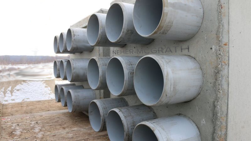
Cable loading, mutual heating, duct layout, soil conditions, and thermal backfill can all affect a cable rating. We evaluate these factors together to help you assess a new design or investigate an existing installation.
02 / EXPERT WITNESS
Expert Witness Services
When underground electrical systems fail, we provide expert witness services to support your needs.
Proprietary Software
Our proprietary software development draws on more than 20 years of experience performing Neher–McGrath calculations. We’re developing packages for underground cable ampacity and duct-bank thermal analysis and will post demonstrations as they become available.
Explore our Cable View software
Engineering Videos
We’ll share videos we’ve developed over the years to explain underground cable ampacity, duct-bank heating, and thermal backfill.
Technical Resources
01 / METHOD
Calculation Method
See how the Neher–McGrath method relates heat from loaded cables to how readily it moves through the duct bank and surrounding soil.
02 / MATERIALS
Thermal Backfill
See how thermal backfill and concrete mix choices affect heat transfer around buried ducts.
03 / FIELD NOTES
Frequently Asked Questions
Find answers on duct-bank configuration, soil moisture, and heat transfer.
Neher-McGrath Method
In electrical engineering, Neher–McGrath is a method of estimating the steady-state temperature of electrical power cables for some commonly encountered configurations. By estimating the temperature of the cables, the safe long-term current-carrying capacity of the cables can be calculated.
The history of NEC Table 310-15
Starting in 1889, many attempts were made to find the correct ampacity for conductors in order to prevent conductor temperatures that exceed the insulation rating.
In 1889, Arthur Edwin Kennelly published a paper with tables listing a rating of 46 A for a #10 copper conductor.
The following year H.W. Fisher listed 19 A, and in 1894 the Underwriters’ Electrical Bureau listed 20 A for the same conductor.
By the end of 1937 various organizations listed at least 14 different ampacities for the same size conductor.
In 1938, Samuel J. Rosch, a member of the American Institute of Electrical Engineers (AIEE) and head of product development for the Anaconda Wire and Cable Company, conducted an investigation to determine the correct ampacities for all the standard size conductors used at that time.
The first step was to establish the maximum continuous operating temperature for insulation. Rosch performed deterioration tests in environmental test chambers.
He connected thermocouples to the wire, applied voltages, and measured ampacities and temperatures.
The results were published in March 1937 in "The Current-Carrying Capacity of Rubber-Insulated Conductors."
This publication became the baseline of Table 310-15 of the National Electrical Code. Rosch’s original table was based on an ambient temperature of 30°C and a conductor temperature of 50°C for industry-standard rubber of the time.
If we convert the ampacities in The Current-Carrying Capacity of Rubber-Insulated Conductors publication to 60°C using the NEC formula, set delta TD to 0 for voltages below 600 V, and round to the nearest 5 A, we can calculate the ampacities for 60°C insulations as found in the first column of Table 310-15.
The same calculation was used to determine the ampacities in the 75°C and 90°C columns in Table 310-15.
Issues with Table 310-15
There are some limitations to Rosch’s paper.
- He did not investigate the effects of mutual heating from adjacent heat sources.
- His paper only considered aboveground installations.
- Voltages higher than 600 were not investigated. For most installations, load calculations performed according to Article 220 provide enough safety margin to prevent these issues.
To clarify this, a fine-print note was added to the NEC for determining conductor sizes on loads calculated in accordance with Article 220.
In the 1950s, when the industry began to see very large and continuous loads on systems, utilizing underground feeder runs in underground duct banks, the issues in Rosch’s paper surfaced.
In cases where load calculations used engineering methods in place of Article 220 and conductor sizes were selected using Table 310-15, conductors overheated. This problem was particularly evident in the conductors located nearest the center of the duct banks.
Rosch used the Fourier heat transfer equation, adding the variable "n" for the number of conductors in the same raceway.
But that modified equation had no variable to adjust the ampacity for heat that came from adjacent sources, or for the differences in the thermal insulation of the soil or concrete in an underground installation.
In 1957, J. H. Neher and M. H. McGrath published a paper that solved these issues. The paper titled "The Calculation of the Temperature Rise and Load Capability of Cable Systems" now known as the Neher–McGrath paper, showed that center conductors in a three-by-three duct bank would need to be derated to almost 60% because of the mutual heating effect from adjacent ducts in duct banks.

Where:
Tc = conductor temperature (°C)
Ta = ambient temperature (°C)
ΔTd = dielectric loss temperature rise
Rdc = dc resistance of conductor at temperature Tc
Yc = component ac resistance resulting from skin effect and proximity effect
Rca = effective thermal resistance between conductor and surrounding ambient
However, this single equation masks the great complexity involved in these procedures. There are scores of complicated equations involved in developing the terms in this equation and those required for temperature calculations. (The paper defines over 80 variables and contains in excess of 70 formulas excluding appendices.) To solve for unique ampacities or temperatures at each cable position, a set of simultaneous equations must be developed to take into account interference heating from every position in the system, and a matrix technique must be used to solve them.
There are many software packages sold today that will perform this complex calculation. Some of these systems are very good, and some are weak or poorly designed. The package you buy is dependent on the complexity of the calculation you need to perform and how much tolerance you have for a steep learning curve and your budget. As discussed above, there are numerous variables that you need to know and understand fully before you can even start the calculation. Let’s say you have the software and the required system variables, and you perform a calculation. Now you have the results, and you are halfway home. Much like an X-ray, the information is only as good as the doctor who analyzes it. It takes years to truly understand all the results and find the most cost-effective solution. There are numerous ways to mitigate heat in an underground installation. Some are easy and may have little or no cost, and some can be extremely expensive and time consuming for the project.
We are constantly being asked to fix issues caused by engineers that are not truly qualified to interpret the calculation results or caused by contractors that did not understand how to install the underground system per the engineer’s specifications
We are also involved in litigation as expert witnesses where there were failures in the underground electrical installation.
Related services
Contact Lane Coburn & Associates for engineering support. See also electrical expert witness services.