.: Neher-McGrath Equation
The Neher-McGrath Calculations is a method for calculating underground cable temperatures and cable ampacity ratings. The Calculations method derived from:
J. H. Neher and M. H. McGrath,"The Calculation of the Temperature Rise and Load Capability of Cable Systems", AIEE Transactions, Part III, Volume 76, pp 752-772, October, 1957.
This paper considers the heat transfer issues associated with underground system ampacities. The paper cites the following basic equation for calculation of a cable ampacity:
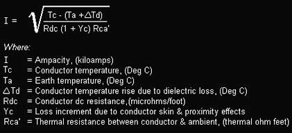
However, this single equation masks the great complexity involved in these procedures (see calculation example). There are scores of complicated equations involved in developing the terms in this equation and those required for temperature calculations. (The paper defines over 80 variables and contains in excess of 70 formulas excluding appendices.)
To solve for unique ampacities or temperatures at each cable position, a multiple set of equations must be developed to take into account interference heating from every position in the system, and a matrix solution technique for simultaneous equations utilized.
Many of ampacity calculations we use today are based on a 1957 paper by J.H. Neher and M.H. McGrath. Later work by CIGRE (INTERNATIONAL COUNCIL ON LARGE ELECTRIC SYSTEMS) documented an ampacity procedure into an international standard (IEC-287 and IEC-853) that provides a step-wise approach to calculating ampacity based upon cable construction.
The two calculation approaches give similar results, although their treatment of daily load cycles is different.
The paper by Neher and McGrath assumes a sinusoidal load shape and uses a 24-hour (daily)
loss factor to account for an overall "averaging" effect of heat output from the cable beyond a
certain diameter (called DX). Within this diameter, the temperature rise across the thermal
resistances in the cable and nearby soil is proportional to the peak heat output from the cable.
At distances greater than this diameter away from the cable center, the temperature rise is
proportional to the average daily heat output.
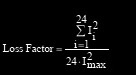
Many system planners are familiar with a "load factor" which relates the peak load to the
average daily load. In cable systems, we are interested in heat output � a function of I2R �
so we use the daily "loss factor", which is essential the load factor of the losses as defined by the
following equation:
Concept of Ampacity
An underground cable circuit rating, or “ampacity”, is the solution to a basic heat transfer
problem. Heat generated in the cable is removed by thermal conduction to ambient earth and,
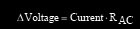
ultimately, air. Engineers familiar with Ohm’s Law know that electrical current flowing through
an resistance will produce a voltage drop according to the following relationship:
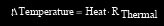
An analogous relationship may be used to describe thermal conduction where heat flowing
through a thermal resistance produces a temperature drop (or rise) according to the following:
This basic concept is extended to model heat out of a buried cable through the various cable
layers, trench backfill and native earth.
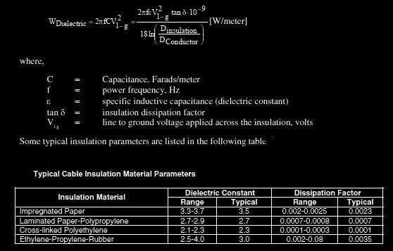
Dielectric Heating
Dielectric heating comes from charging and discharging the insulating dielectric at 50 or 60
times per second. The dielectric heat loss, WDielectric, can be found from the following equation:
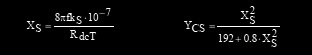
The AC resistance increment for conductor skin effect, YCS, can be found from the following
equation, where kS is the skin effect factor based on the conductor construction.
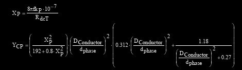
The AC resistance increment for conductor proximity effect, YCP, can be found from the
following equation, where kP is the proximity effect factor based on the conductor construction.
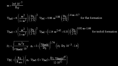
Shield Loss Increments for Eddy Currents
Eddy current losses occur when a continuous concentric metallic layer exists around the cable
core (e.g., a corrugated or extruded metal sheath or longitudinally taped metallic shield, but not
to stranded shields). Also, eddy currents are negligible for pipe-type cables.
The mechanics for calculating the eddy current losses is somewhat onerous but not particularly
complicated. The equations to perform these calculations were derived empirically and are listed
below. For a more detailed explanation, please see IEC-287.
Terms
.: Neher-McGrath Certification
The Neher-McGrath Institute
The Neher-McGrath Institute can provide you with information on how you can achieve the Neher-McGrath certification for your critical environment.
|
|
.: Professional Engineering
Neher-McGrath are specialized and complicated calculations. We highly suggest that all results and calculation be made under the guidance of and licence professional engineer that specializes in this type of work.
NEC 310.15 (C) Engineering Supervision, indicates that these calculations should be performed under engineering supervision.
We have certified Professional Engineeres (P.E) that specilize this this issue ready to assist you on your project in the following states:
| Washington |
Montana |
| California |
Nevada |
| Utah |
Alaska |
| Hawaii
|
Arizona |
| Idaho |
Virginia |
| Pennsylvania |
Oregon |
| |
|
|
|
|
|
|
|
|
|
|
|
.: Software:
There are several software packages available that will calculate the Neher-McGrath equations. Each of these packages has its pros and cons. Please feel free to email us with your particular project requirements and we can help you find the software package that best suits your needs. Email Us
If you would like to submit your software for testing please Email Us
.: Professional Articles :
-Heating- Pure Power Spring 08
-Duct Bank Heating Calculations are Essential
.: DuctShow©:
By downloading you agree that DuctShow� movies are Proprietary and for demonstration purpose only. The information shown in the DuctShow� movies below are NOT applicable to any and all real world installations.
.: Special LowRHO® concrete Mix:
High strength LowRHO� Mix Design -
Compressive Strength
psi 3000
Low strength LowRHO� Mix Design-
Compressive Strength
psi 100-250
.: RHOMON® Conduit Thermal Couplings:
RHOMON� Conduit Thermal Couplings are specially engineered pieces of conduit that are placed in your duct bank during installation. These units monitor temperature and can be set up in a self contained system or tied into the building BMS system
|